Wira Azmoon - Project Portfolio Page
- Overview
- Summary of Contributions
Overview
- Team lead: Responsible for overall project coordination.
- Documentation: Responsible for the quality of various project documents.
- PlantUML expert: Helps other team members with matters related to PlantUML.
-
In charge of
Parser,Uiof the code: In charge of the code that deals with parsing and UI.
Summary of Contributions
Code Contributed
This is the RepoSense report of the code contributed.
Enhancements Implemented
Code, Packages Setup
Set up the skeleton code used in the project, including the following classes:
ParserUiCommandComponent
Introduced the Add Component feature, refactored the Component classes, added the classes within the command package, updated the Parser class, and update some Template classes, as well as Ui and Duke. JavaDoc was also added to Command.execute() methods.
Unit Testing & Assertions
Updated various classes mentioned above. Added classes AddCommand and SetCommand and JUnit Tests ParserTest.
Refactored code according to updated Design Architecture - reduced coupling between Ui and Command to follow Architecture in updated Developer Guide. Added assertions to make the code more defensive.
Boolean Commands Setup
Added/Updated classes in the commands.gates, model.component, model.binarytree packages, as well as updated the BooleanParser to handle new commands.
Added functionalities for BooleanCommand and its subclasses.
PED Bugs
- PR: #156
Squashed bugs found in the PE Dry Run. These included high severity bugs such as #148, #151, with some other medium and low severity bugs as well.
User Guide
Set up the first draft of User Guide for the project, starting with all commands discussed in the initial group meeting in #9, #45. Updated User Guide with v2.0 commands in #59, and updated their expected outcomes in #61. Numerous PED Bugs were also squashed in #158, with many of them being high severity, as can be seen in #154. Finished up the final submission in #173.
Developer Guide
Created structure of Developer Guide, starting with Architecture in #45. Created UML Diagrams with the help of PlantUML, including Class Diagrams found in the Architecture and Sequence Diagram for SetCircuitCommand. As the IC for documentation, improvements were also made to diagrams made by other group members, such as the Class Diagrams found under the Implementation of Boolean Commands. User Stories discussed by the group were also added into its own section.
Review/Mentoring
Almost all PRs were reviewed, with the notable ones listed below:
- #19, #21, #27, #34, #35: Spotted minor fixes
- #23, #26, #38, #41, #43, #51, #56, #62, #63, #90, #93, #100, #116, #160, #161, #169: Gave minor suggestions accepted by teammate
- #42, #54, #92: Gave a number of suggestions accepted by teammate
- #75: Gave many suggestions accepted by teammate, taking the role of PlantUML expert
Beyond Project Team
Forum Posts
- Special Characters in CLI
- Using Tables and Emojis on Github pages
- Question on Assertion and Exception
Forum Comments
Extract: User Guide - Adding a Gate
To aid the user in understanding the User Guide, informational boxes such as below are put in the appropriate commands. The example is from 7.3 Adding a Gate.
The application has the ability to combine multiple
Gateobjects to generate more complicated boolean logic gate configurations. This command allows you to set an input to a boolean logicGate. You can also change an existing gate if needed. However, the depth of the deepest logicGatefrom the root logicGate(at the top) cannot exceed 2.
Gate.
Gate depth cannot exceed 2.
Gate objects to be 2 levels deep, counting from 0 at the top. This means you may see inputs up to the 3rd level, up to the letter O.
| Command Format |
|---|
add INPUT GATE |
Extract: Developer Guide - Logic Class and Sequence Diagrams
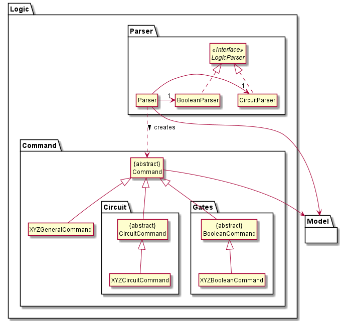
To better showcase the relationships between the various classes used in the project, the following UML diagrams were used to explain the Architecture of the application. A reference frame was also used so that the diagrams explained in the later section could be more concise. The following example is from Logic Component.

Figure 4
Logicstores a currentTemplateobject inModelthat represents the current circuit configuration.Logicuses theParserclass to parse the user command.- This results in a
Commandobject which is executed inDuke.- The command execution can affect the
Model(e.g. setting a value).
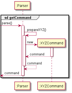
In general, the creation of
Commandobjects viaParsercan be explained by the following sequence diagram, which acts as a reference frame forgetCommand:

Figure 5
If the command does not use the reference frame, they would have their own sequence diagram to showcase the difference.