Vishruti Ranjan - Project Portfolio Page

- Overview
- Summary of Contributions
Overview
- Integration: Responsible for overseeing integration of project scripts written by different members.
- IntelliJ expert : Helps other team members in matters related to IntelliJ.
-
In charge of
Commandcode: In charge of the code that deals with different commands, and their execution based on user input.
Summary of Contributions
Code Contributed
This is the Reposense report of the code contributed
Enhancements Implemented
Basic Template Code Setup
- PR: #23
Set up the code for circuit templates, beginning with class Template and LrTemplate (Inductor-Resistor Circuit Template).
Calculate Command for Circuit Template
- PR: #38
Added the effective calculation command for the circuit template to be able to calculate and print:
- effective resistance
- effective capacitance
- effective inductance
- total current
- total power In the current circuit template chosen.
Interactive Tutorial for Circuit Commands and Initial Summary Command
Added the interactive tutorial feature for circuit commands to the application as well as the initial command summary table. Based on feedback from the PE-D made the tutorial more user-friendly.
Calculate Command and Binary Tree for Boolean Template
Added the effective calculation command for the boolean template to be able to calculate and print the total output of the current logic gate configuration.
Also updated classes in model.binarytree and class BooleanTemplate to create a simple visual representation of the boolean logic circuit and added binary tree implementation for the logic circuits.
Unit Testing, Assertions and Logging
Added unit testing for CalculateBooleanCommand, Ui and CalculateCircuitCommand.
Added assertions to AddCircuitCommand.
Set up logging in Duke.java and added logging to TutorialCircuitCommand, Command, ExitCommand, TemplateCommand and Parser.
PE-D Bugs
Squashed PE-D bugs related to Interactive Tutorial for Circuit Commands and added exception customisation for `model.
User Guide
- PR: #168
Added annotated images for calc command sections and bye command.
Developer Guide
Added the section on implementation considerations describing the rationale behind implementing a logic circuit using a binary tree-like data structure.
Also, added section describing the BinaryTree<T> class and all its noteworthy public methods employing the use of object and sequence diagrams to aid the reader in understanding how the functions work.
Added the glossary of the guide.
Review/Mentoring
- #18, #36, #52, #56, #86: Suggestions, some minor and some major.
- #39, #157: Minor suggestions accepted by team-mate. (Co-Authored)
Beyond Project Team
Forum Contribution
Extract: User Guide
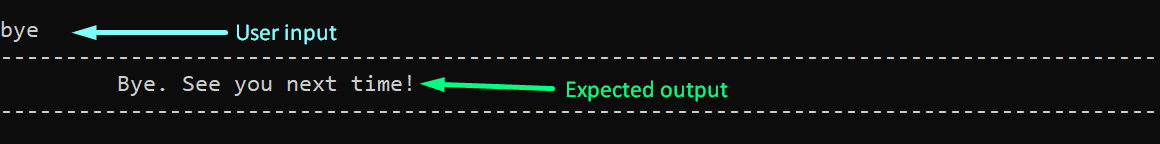
5.3 Exiting the Application
This command can be used to exit the application.
| Command Format |
|---|
bye |
The following diagram shows the expected behaviour when using the bye command.
Extract: Developer Guide
Rationale Behind Using Binary Heap-Like Data Structure
Selecting the appropriate data structure for emulating a logic circuit is an important aspect to consider whilst building such a system. The following table depicts the properties of a Binary Heap-Like structure mapped to the application’s requirements.
| Requirements | Property of Binary Heap |
|---|---|
| Connects different gates together | A binary-heap, being a type of binary tree, is a connected graph. |
| Easily stored | Can be stored in simple contiguous memory like an Array/ArrayList |
| Easy to print | Nodes stored in an array, rather than a graph-like structure |
| Inputs can be easily manipulated | Manipulating augmented values involves a simple O(1) operation. |
| Emulate 2-input logic circuit | Being a binary tree, each node can have atmost 2 children, thus recreating a 2-Input Logic Gate |
Therefore, since the Binary Heap-Like data structure best-fits the requirements for the system, the data structure was selected to implement the logic circuit.
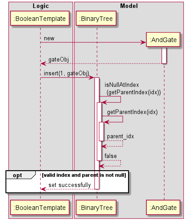
Sequence Diagram Example
The following image is one of the sequence diagrams added to the Developer Guide under the BinaryTree<T> section.