User Guide
- 1. How To Use This Guide
- 2. Introduction
- 3. Quick Start
- 4. Command Preface
- 5. General Commands
- 6. Circuit Action Commands
- 7. Boolean Action Commands
- 8. FAQ (Dash)
- 9. Command Summary
- 10. Glossary (Wira)
1. How To Use This Guide
This User Guide aims to help you get familiarised with the commands used in this Command Line Interface (CLI) application. The following table indicates the symbols used to aid the understanding of the guide. The end of this User Guide also gives a summary of commands used in the application.
| Symbol/Format | Meaning |
|---|---|
| An informational source. | |
| A warning. | |
| A tip. | |
| Bolded | A keyword. |
| Italicised | Technical word. |
| Hyperlinked | Leads to the appropriate section. |
Code |
Text that appears on the CLI / in code. |
2. Introduction
CLIrcuit Assistant is a desktop app designed to implement and solve simple circuits and logic gate configurations, optimized for use via the CLI. The application is targeted at those who would prefer using a resource-light and offline program to aid in analysing circuits.
In its current implementation, this application has no storage feature. More information on this can be found in the Developer Guide.
3. Quick Start
The following section will explain the steps taken to get CLIrcuit Assistant running on your computer.
- Ensure that you have Java 11 or above installed.
- Download the latest version of
CLIrcuit Assistantfrom the releases. - Double click the
jarfile to start the application.- If the above step does not open the app, then open your terminal and make sure you are in the folder with the
jarfile. - Type the following command:
java -jar CS2113T-W13-3.CLIRCUIT_ASSISTANT.jar
- If the above step does not open the app, then open your terminal and make sure you are in the folder with the
- Once the app starts, type a command in the command line and press enter to execute it.
- Use the command
tutorial circuitortutorial booleanto go through an interactive tutorial before using the application. - Alternatively, you can use the command
summaryto get a list of all commands used in the application. - Note that a logging file
appLog.txtwill be created in the same directory thatCS2113T-W13-3.CLIRCUIT_ASSISTANT.jaris run from. For further information regarding logging, you can refer to the Developer Guide.
4. Command Preface
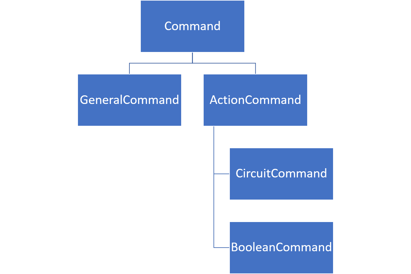
The diagram above shows the hierarchy of the types of commands in the application. If you are looking for the summary of commands used within the CLI app, it can be found at the end of this guide. In this User Guide, you can find the following sections as listed below:
General commands are commands which are not specific to features available using the action commands.
Action commands are split into two categories - circuit and boolean. They may use the same syntax for some commands, but the application will continuously track the current template that is being worked on and automatically use the correct command to execute. Thus, if there is no current template, then the other commands used will not be available to run.
template command is essential.
The commands usable in both categories are:
templatesetaddcalc
The format required for the commands are as follows:
UPPER_CASE are parameters.
5. General Commands
This section details the generic commands that can be used. These commands assist you in finding out generic information regarding the application.
5.1 Summary of Commands (Dash)
This command prints a summary of all commands in the application as shown in Command Summary.
| Command Format |
|---|
summary |
The image below shows the expected summary tables where the first table lists the commands and the second table
lists all the parameters for the commands. This is as shown with the command summary.
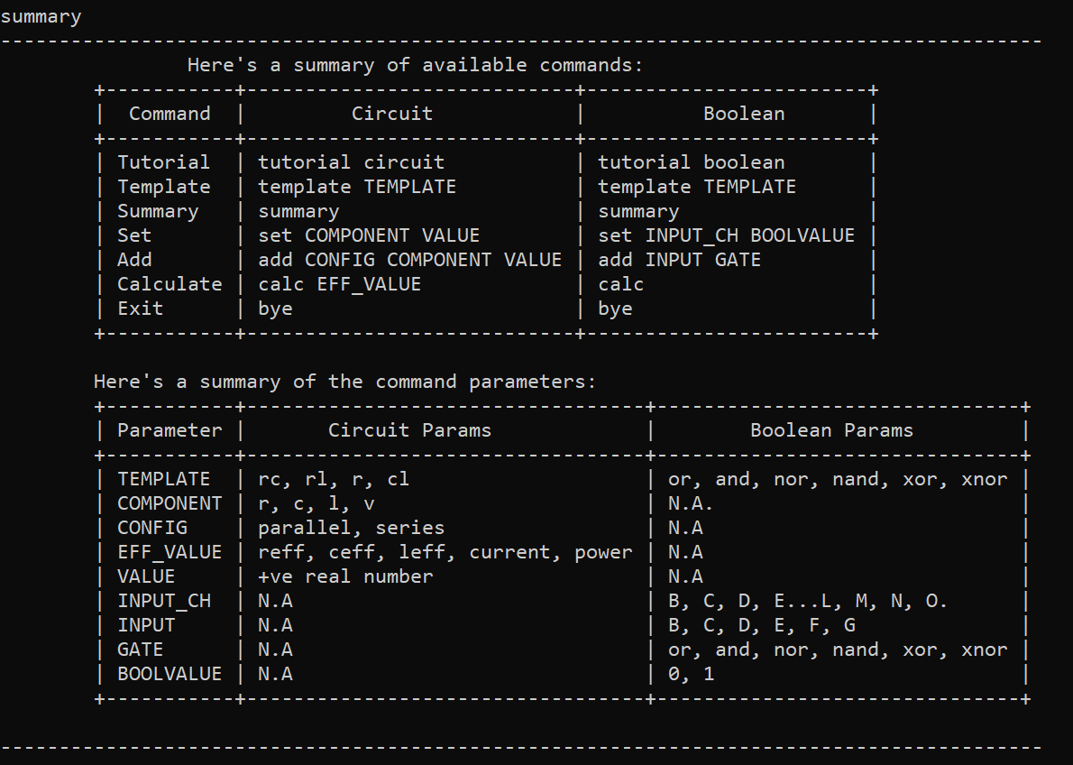
Figure 2
5.2 Interactive Tutorial (Praveen)
To aid the user, this command starts the interactive tutorial for either the Circuit Action Commands or Boolean Action Commands based on the parameter specified.
| Command Format |
|---|
tutorial TYPE |
-
TYPEcan be eithercircuitorboolean.
Once you have entered the interactive tutorial, you are to follow the instructions provided to you as follows:
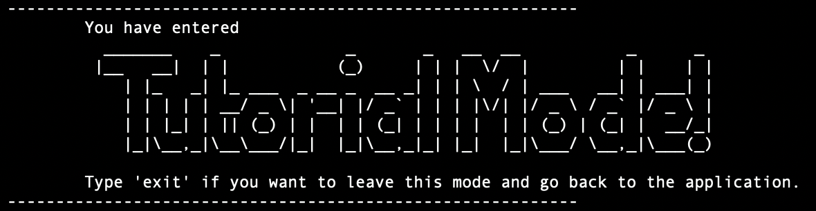
Figure 3
The proceeding instructions will depend on whether you have chosen tutorial circuit or tutorial boolean.
When you have entered the tutorial, you will be required to type in the commands in the terminal for each step of the tutorial as per the instructions given to them.
You will be required to do this until you have reached the end of the tutorial.
When you have typed in a command that is inconsistent with what is required as per the tutorial’s instruction for that particular step, an invalid command message will be returned until you type in the correct command in the terminal line as shown below.
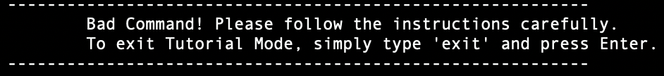
Figure 4
You may also choose to exit the tutorial at that point of
time instead by entering exit. However, it is recommended that you go through the entire tutorial
for both circuit and boolean tutorials at least once to familiarize yourself with the basic commands and how they work.
5.3 Exiting the Application (Vishruti)
This command can be used to exit the application.
| Command Format |
|---|
bye |
The following diagram shows the expected behaviour when using the bye command.
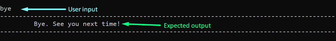
Figure 5
6. Circuit Action Commands
This section details how the commands are used with a circuit template. You can use this section to build simple template circuits which may have a voltage source with load components such as resistors, capacitors, or inductors.
It may be important to note that the circuit diagrams shown in the expected outputs are simplified circuits, even when adding components. For example, adding a resistor in parallel to a template that contains a resistor will change the effective resistance in the circuit, but it will not dynamically update the visualised diagram to show a second resistor. This can be seen more clearly once you create a circuit template.
6.1 Creating a circuit template (Wira)
This command creates a circuit template. This command must be used to be able to use the set, add, calc commands since those commands must be done on an existing template.
| Command Format |
|---|
template TEMPLATE |
- The
TEMPLATEcan be chosen from the following 4:-
ronly consists of the resistor. -
rcconsists of the resistor and capacitor. -
rlconsists of the resistor and inductor. -
lcconsists of the inductor and capacitor.
-
The diagram below shows an example when using the template rc command.
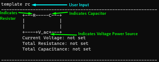
Figure 6
6.2 Setting a component value (Praveen)
This command sets the value of a component. The component must be part of the current circuit template. Units correspond to the component involved - resistors in ohms, capacitors in microfarads, and inductors in microhenries. The values would need to be set to perform calculations or analysis such as in the calc command.
| Command Format |
|---|
set COMPONENT VALUE |
- The
COMPONENTcan be chosen from the following 4, but only if they are part of the template:-
rrepresents a resistor -
crepresents a capacitor -
lrepresents an inductor -
vrepresents a voltage source
-
- The
VALUEcan be an integer of a float, of which the units depends on the component being set.
The image below shows an example of using the command set r 500 on the template shown.
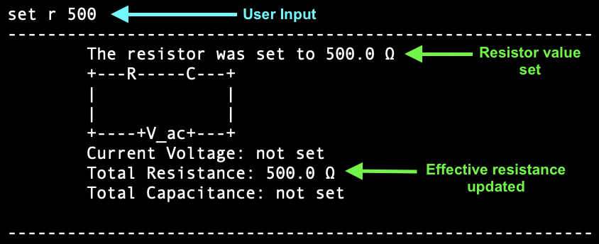
Figure 7
6.3 Adding a component (Wira)
This command adds a component in a specific configuration - either in parallel or in series - to the current circuit template. This allows you to quickly obtain calculations to your chosen configurations. Only load components can be added - you cannot add a voltage source. You should only add a component after it has already been set.
set command.
v to any template.
| Command Format |
|---|
add CONFIG COMPONENT VALUE |
- The
CONFIGcan be chosen from the 2 -seriesandparallel. - The
COMPONENTandVALUEare as explained above under Set component value, except thatCOMPONENTcannot be the voltage sourcev.
The image below shows an example of using the command add parallel r 500 on a template.
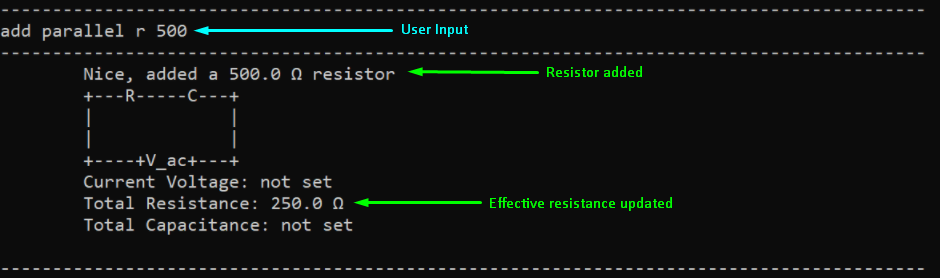
Figure 8
6.4 Calculating Effective Value (Vishruti)
This command calculates the various effective values based on the template configuration. While calculating reff, ceff, or leff, the component must be part of the current circuit template. You can quickly obtain the various values detailed below after setting the necessary components.
| Command Format |
|---|
calc EFF_VALUE |
- The
EFF_VALUEcan be chosen from the following 5:-
reffis the effective resistance -
ceffis the effective capacitance -
leffis the effective inductance -
currentis the current flowing through the power supply -
poweris the power supplied by the power supply
-
The image below is an example of when the calc power command is entered.
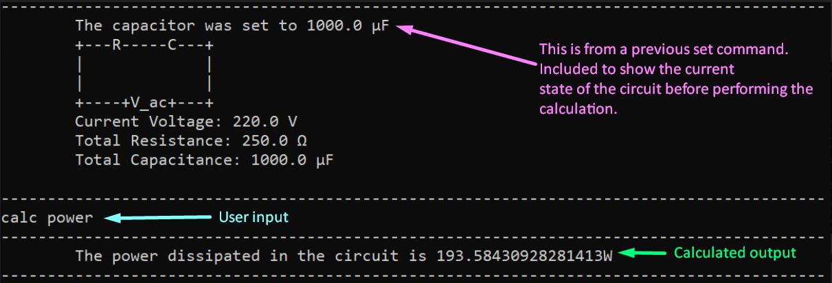
Figure 9
7. Boolean Action Commands
This section details how the commands are used with a boolean template. You can use this section to build simple logic circuits which may be made up of various gates such as AND, OR, and XOR gates.
7.1 Creating a boolean template (Dorian)
This command creates a boolean template. Similar to the circuit template, this command must be used to be able to use the set, add, calc commands since those commands must be done on an existing template.
? denotes an input that is not yet set.
| Command Format |
|---|
template GATE |
- The
GATEcan be chosen from the following:-
and,or,xor,nand,nor,xnor
-
The image below shows an example when using the template and command.
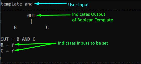
Figure 10
Here, OUT represents the output of the boolean template. The letters B and C can correspond to INPUT which is used in the following section. ? represents an INPUT which is not yet set.
7.2 Setting an input value (Praveen)
This command sets the value of an input. The inputs will then be used in the calc command to give the output of the boolean template. The input must not have already been set as a Gate and must be part of the diagram.
INPUT must exist in the diagram, and must not have already been set as a Gate.
| Command Format |
|---|
set INPUT VALUE |
- The
INPUTcan be chosen only from letters seen in the currenttemplate. - The
VALUEcan be any integer, but any valid non-zero integer will be treated as1, while 0 is treated as0. Valid integers are defined as the Javainttype.
The image below shows an example of using the command set B 0 on the template shown.
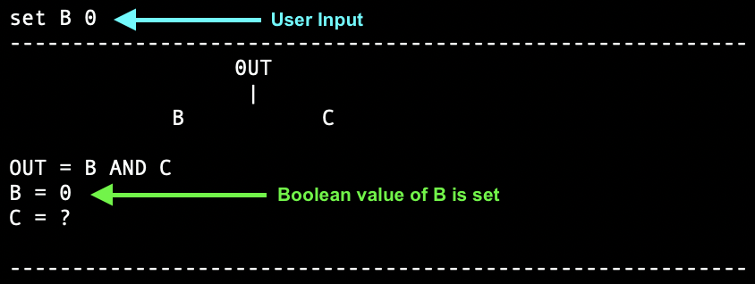
Figure 11
7.3 Adding a Gate (Wira)
The application has the ability to combine multiple Gate objects to generate more complicated boolean logic gate configurations. This command allows you to set an input to a boolean logic Gate. You can also change an existing gate if needed, except for the root Gate, which would require a new template. However, the depth of the deepest logic Gate from the root logic Gate (at the top) cannot exceed 2.
Gate, except for the root Gate.
Gate depth cannot exceed 2.
Gate objects to be 2 levels deep, counting from 0 at the top. This means you may see inputs up to the 3rd level, up to the letter O.
| Command Format |
|---|
add INPUT GATE |
The image below shows an example of using the command add C or on the template shown.
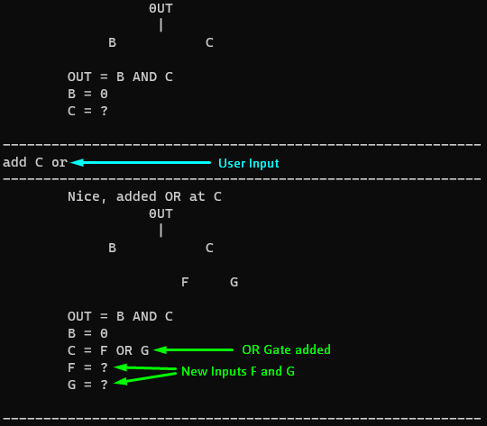
Figure 12
7.4 Calculating Output (Vishruti)
This command calculates the output of the configured logic gates, and requires that all inputs of the circuit are set. The output is represented by OUT in the printed template.
| Command Format |
|---|
calc |
The following image shows an example of using the calc command.
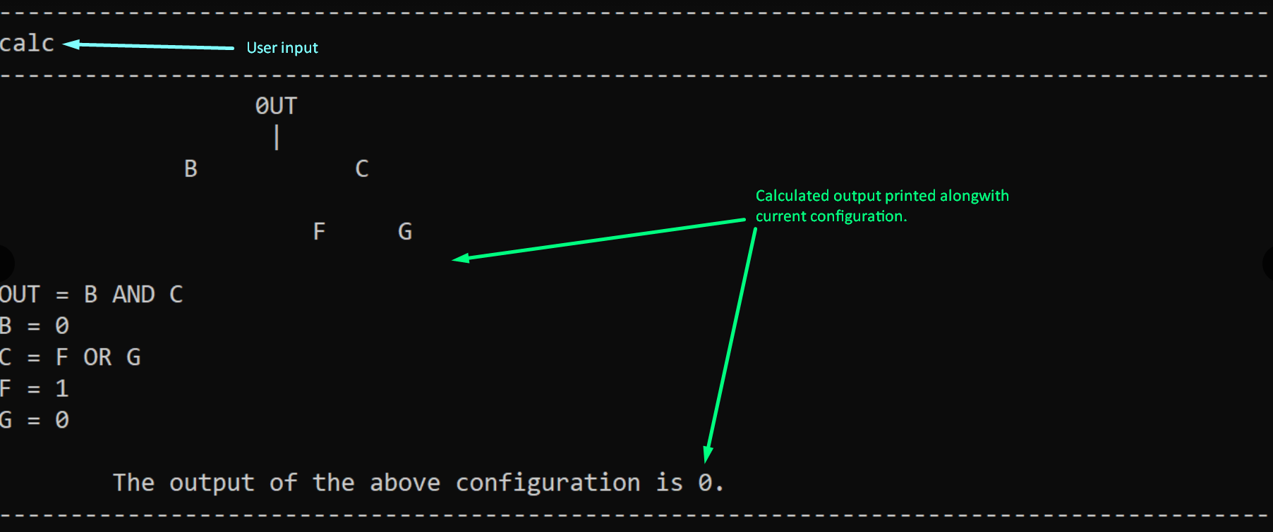
Figure 13
8. FAQ (Dash)
This section details the frequently asked questions (FAQ) regarding the use of the application.
Q: How do I know what each component does?
A: The components are derived from basic circuit theory that is covered in detail in the module CG1111: Engineering Principles and Practice I. Basic understanding of this module is enough to familiarise you with each of the components and what they do.
Q: How do I know what each logic gate does?
A: Logic Gates are basic elements of electrical design that can be read and understood easily through various online resources. This is covered in detail in the module EE2026: Digital Design. Basic understanding of this module is enough to familiarize you with each of the logic gates and how they operate.
Q: Why is the interactive tutorial so restrictive?
A: Given that this is a tutorial, the goal here is to make sure that you know how to use each and every feature of this application. However, you are allowed to exit the tutorial at any point of time and be able to use the full functionality of this application.
Q: Why does using the add command for the circuit template give me a “Component not yet set” error?
A: You have to first set the component involved using the set command.
Q: Why can’t I calculate the output from the logic circuit I created?
A: You have to make sure all inputs to the gate have been set.
9. Command Summary
This section summarises the commands used in the application.
| Action | Format, Examples |
|---|---|
| Tutorial |
tutorial TYPE e.g., tutorial circuit
|
| Summary | summary |
| Template Circuit/Logic Gate |
template TEMPLATE/GATE e.g., template rc e.g., template and
|
| Set Circuit/Logic Gate |
set COMPONENT/INPUT VALUE e.g., set r 500 e.g., set B 0
|
| Add Circuit |
add CONFIG COMPONENT VALUEe.g., add parallel c 500
|
| Add Logic Gate |
add INPUT GATEe.g., add C or
|
| Calculate Circuit/Logic Gate |
calc EFF_VALUE/[] e.g., calc ceff e.g., calc
|
10. Glossary (Wira)
This section explains certain technical terms used in the guide which may require more detail.
| Term | Explanation |
|---|---|
| capacitors | A component which stores electrical energy in an electrical field |
| Command Line Interface (CLI) | Text-based user interface which the application uses to interact with the user |
| current | Flow of electric charge in a circuit |
| inductors | A component which stores energy in a magnetic field when electric current flows throw it |
Java int |
Defined as an integer in the programming language Java which can store numbers from -2147483648 to 2147483647 |
| integer | A whole number |
| load components | A component which consumes electric power |
| logging | Keeping a record of information about events which take place, specific to the application |
| logic gate | Physical electronic device implementing a Boolean function |
| power | Rate at which electrical energy is transferred by a circuit |
| resistors | A component which provides electrical resistance |
| root | A point of reference for which other points can be traced back to |
| syntax | Rules in which a command must be run |
| voltage source | A device which can maintain a fixed voltage |